| Toolbar | Modify |  |
| Pull-down | |
| Keyboard | EXTEND | short-cut | EX |
 This command extends a line, polyline or arc to meet another drawing object (known as the boundary edge). In the illustration on the right, two lines (red) are extended to meet another line (cyan) which forms the boundary edge. This command works in a similar way to the Trim command, described above. Two selections are made, one for the boundary edge(s) and one for the object(s) to extend.
 Lines and other objects can be extended in one of two directions. In the illustration on the right, the red line could be extended either to the right or to the left. You can tell AutoCAD in which direction to extend by picking a point to the right or left of the midpoint respectively. AutoCAD does not intuitively know where the boundary edge lies so you must explicitly indicate the direction of extension by picking either one side or other of the midpoint.
Draw the lines as shown in the illustration and follow the command sequence below.
Command Sequence
Command: EXTEND
Current settings: Projection=UCS Edge=None
Select boundary edges ...
Select objects: (select the boundary edge, P1)
Select objects:  (to end boundary edge selection)
Select object to extend or shift-select to trim or [Project/Edge/Undo]: (pick the object which you want to be extended, P2)
Select object to extend or shift-select to trim or [Project/Edge/Undo]: (pick another object which you want to be extended, P3)
Select object to extend or shift-select to trim or [Project/Edge/Undo]: (to end)
Sometimes you may get the message "Object does not intersect an edge" or "No edge in that direction". If this happens it means that you are either picking the wrong end of the object or the object you are trying to extend will not meet the boundary edge. The solution is either to pick near the end you want to extend or to move the boundary edge so that the extended line will intersect with it.
Using Edgemode
If the line you are trying to extend does not intersect with the boundary line, you can use the "Edge" option to toggle Edgemode to "Extend" (the default is "No Extend"). When the Extend command is set to Extend Mode, the objects being extended will extend to an imaginary line through the boundary edge, irrespective of whether the extended object actually intersects with the boundary edge. This is particularly useful and can save lots of time.
 The illustration on the left shows the result of extending a line (red) to a boundary edge (cyan) with Edgemode set to "Extend". The same process would have resulted in an error message if Edgemode had been set to "No Extend". To get a better understanding of how this works, draw the two lines as shown in the illustration and try to extend them using the default settings. When you have done that, follow the command sequence below.
Command Sequence (Edgemode)
Command: EXTEND
Select boundary edges: (Projmode = UCS, Edgemode = No extend)
Select objects: (select the boundary edge, P1)
Select objects: (to end boundary edge selection)
Select object to extend or shift-select to trim or [Project/Edge/Undo]: E (to use the Edge option)
Enter an implied edge extension mode [Extend/No extend] : E (to set Edgemode to Extend)
Select object to extend or shift-select to trim or [Project/Edge/Undo]: (pick the object to be extended, P2)
Select object to extend or shift-select to trim or [Project/Edge/Undo]: (to end)
Notice that the current value of Edgemode is always displayed on the command line when you start the Extend command. The Edge option can also be used with the Trim command to enable trimming to cutting edges which do not actually intersect the object to trim. Edgemode is a system variable, so any change to its value will affect both the Trim and Extend commands.
See the Lengthen command for more ways to extend and trim objects.
Shift Selection with Trim & Extend
You may have noticed during the command sequences for the Trim and Extend commands that you have the option to "shift-select". This feature is new to AutoCAD 2000i and it enables you to extend while using the Trim command and to trim while using the Extend command. These two commands are very closely related and you often need to trim and extend objects at the same time. If you are a beginner with AutoCAD it may be a good idea to avoid this feature initially, the Trim and Extend commands can be tricky to get to grips with in any case. However, do remember this feature because it is a great time saver.
| Toolbar | Modify | |
| Pull-down | |
| Keyboard | EXTEND | short-cut | EX |
This command extends a line, polyline or arc to meet another drawing object (known as the boundary edge). In the illustration on the right, two lines (red) are extended to meet another line (cyan) which forms the boundary edge. This command works in a similar way to the Trim command, described above. Two selections are made, one for the boundary edge(s) and one for the object(s) to extend.
Lines and other objects can be extended in one of two directions. In the illustration on the right, the red line could be extended either to the right or to the left. You can tell AutoCAD in which direction to extend by picking a point to the right or left of the midpoint respectively. AutoCAD does not intuitively know where the boundary edge lies so you must explicitly indicate the direction of extension by picking either one side or other of the midpoint.
Draw the lines as shown in the illustration and follow the command sequence below.
Command Sequence
Command: EXTEND
Current settings: Projection=UCS Edge=None
Select boundary edges ...
Select objects: (select the boundary edge, P1)
Select objects: (to end boundary edge selection)
Select object to extend or shift-select to trim or [Project/Edge/Undo]: (pick the object which you want to be extended, P2)
Select object to extend or shift-select to trim or [Project/Edge/Undo]: (pick another object which you want to be extended, P3)
Select object to extend or shift-select to trim or [Project/Edge/Undo]: (to end)
Sometimes you may get the message "Object does not intersect an edge" or "No edge in that direction". If this happens it means that you are either picking the wrong end of the object or the object you are trying to extend will not meet the boundary edge. The solution is either to pick near the end you want to extend or to move the boundary edge so that the extended line will intersect with it.
Using Edgemode
If the line you are trying to extend does not intersect with the boundary line, you can use the "Edge" option to toggle Edgemode to "Extend" (the default is "No Extend"). When the Extend command is set to Extend Mode, the objects being extended will extend to an imaginary line through the boundary edge, irrespective of whether the extended object actually intersects with the boundary edge. This is particularly useful and can save lots of time.
The illustration on the left shows the result of extending a line (red) to a boundary edge (cyan) with Edgemode set to "Extend". The same process would have resulted in an error message if Edgemode had been set to "No Extend". To get a better understanding of how this works, draw the two lines as shown in the illustration and try to extend them using the default settings. When you have done that, follow the command sequence below.
Command Sequence (Edgemode)
Command: EXTEND
Select boundary edges: (Projmode = UCS, Edgemode = No extend)
Select objects: (select the boundary edge, P1)
Select objects: (to end boundary edge selection)
Select object to extend or shift-select to trim or [Project/Edge/Undo]: E (to use the Edge option)
Enter an implied edge extension mode [Extend/No extend] : E (to set Edgemode to Extend)
Select object to extend or shift-select to trim or [Project/Edge/Undo]: (pick the object to be extended, P2)
Select object to extend or shift-select to trim or [Project/Edge/Undo]: (to end)
Notice that the current value of Edgemode is always displayed on the command line when you start the Extend command. The Edge option can also be used with the Trim command to enable trimming to cutting edges which do not actually intersect the object to trim. Edgemode is a system variable, so any change to its value will affect both the Trim and Extend commands.
See the Lengthen command for more ways to extend and trim objects.
Shift Selection with Trim & Extend
You may have noticed during the command sequences for the Trim and Extend commands that you have the option to "shift-select". This feature is new to AutoCAD 2000i and it enables you to extend while using the Trim command and to trim while using the Extend command. These two commands are very closely related and you often need to trim and extend objects at the same time. If you are a beginner with AutoCAD it may be a good idea to avoid this feature initially, the Trim and Extend commands can be tricky to get to grips with in any case. However, do remember this feature because it is a great time saver.
Read more»
 Let's have a closer look at the selection parameters in the Quick Select dialogue box. As with all dialogue boxes, it is important to move methodically through the various parameters. It is even more important in this case because the choices you make at the beginning of the process will affect the options available to you later. Start at the top of the dialogue with "Apply to" and work your way down.
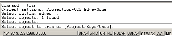
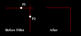 You can use the Fillet command with a radius of zero to trim intersecting lines back to their intersection. Of course, you could also achieve this effect with the Trim command but if you have a number of operations to complete, the Fillet method is much quicker.
 The Fillet command can also be used to fillet arcs and circles. The "Polyline" option also allows you to fillet all vertices of a polyline with a single command. It's worth experimenting with this command, it can save you lots of time and enables you to construct shapes which otherwise would be quite difficult.
 For example, you can easily create the lozenge shape shown on the right from a simple rectangle. Since AutoCAD rectangles are just closed polylines, you can use the Polyline option of the Fillet command to fillet all polyline vertexes simultaneously. Try this for yourself; draw a rectangle and then follow the command sequence below.
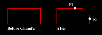

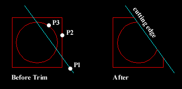 The Trim command can be used to trim a part of an object. In order to trim an object you must draw a second object which forms the "cutting edge". Cutting edges can be lines, xlines, rays, polylines, circles, arcs or ellipses. Blocks and text cannot be trimmed or used as cutting edges. The illustration on the right shows the Trim command in action. The red square and circle have been drawn using the Polygon and Circle commands respectively. In order to trim these objects, a line has been drawn (cyan in the illustration), this forms the cutting edge. The Trim command, unlike most other modify commands requires that two separate object selections are made. The cutting edges are selected first (there can be one or more) and then the objects to be trimmed are selected. In the example above, the line is selected first because it forms the cutting edge and then the square and circle are selected.