| Toolbar | Modify | ||
| Pull-down | |||
| Keyboard | ARRAY | short-cut | AR |
The Array command makes multiple copies of selected objects in a rectangular matrix (columns and rows) or a polar (circular) pattern. This command has been completely transformed in AutoCAD 2000i. It is now completely dialogue box driven with the option to see a preview of the array before it is created. You can also now create rectangular arrays at a user specified angle angle. This constitutes a major improvement in usability.
The Rectangular Array
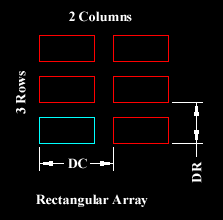
 The illustration on the right shows the results of a rectangular array with two columns an three rows. The distance between rows is indicated with the dimension DR and between columns with DC. When creating rectangular arrays it is important to remember that new rows are created above the original object and new columns are created to the right of the original object. The resulting array is, therefore, always created with the original object in the bottom left hand position with respect to the current co-ordinate system. In the illustration, the original object is shown in cyan and the new objects in red. It is possible to create arrays which do not align with the World Co-ordinate System by setting a User Co-ordinate System first. See the UCS tutorial for details.
Try creating this array yourself. First, draw a rectangle 20 drawing units wide and 10 drawing units tall. To do this, start the rectangle command from the pull-down menu. When you are prompted to pick a point, pick somewhere in the lower left quarter of the drawing area. Then, when you are prompted for a second point, enter the relative cartesian co-ordinate @20,10. You have now drawn a rectangle at the right size. See the Using Co-ordinates tutorial for more information on drawing with co-ordinates.

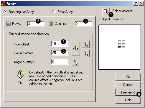
Now start the Array command.First of all, make sure that the Rectangular Array radio button is selected and that you are looking at the Rectangular Array dialogue box and now follow the steps below:
- Click the Select objects button. The dialogue box will temporarily disappear enabling you to select the rectangle you just drew. Press the Return button on your keyboard to complete the selection. You are now returned to the dialogue box and the message immediately below the Select Objects button should read "1 objects selected".
- Enter the number of rows required in the Rows edit box. For this example, enter the value "3". Notice that the schematic preview on the right hand side of the dialogue box updates to reflect the values you are entering.
- Enter the number of columns required in the Columns edit box. Enter the value "2".
- Enter the row offset in the Row Offset edit box. This is the distance DR in the illustration above. Note that tis is not the distance between rows. In this example, our rectangle is 10 units high and we will enter a row offset of 15. The result will be a 5 unit gap between rectangles.
- Enter the column offset in the Column Offset edit box. The same parameters apply as for the row offset. Enter a value of 25 to give a 5 unit gap between our rectangles.
 Click on the Preview button. Once again, the dialogue box disappears and the specified array is temporarily drawn so that we can preview it. We are now offered 3 choices. If the array isn't quite right, click the Modify button to return to the Array dialogue box. If you are happy with the array, click the Accept button, the array will be permanently drawn and the command is ended.
You should now have an array that looks similar to the one in the illustration above consisting of 6 rectangles arranged in 3 rows and 2 columns. As you can se, this command is very powerful and can save lots of time if used carefully.
The Polar Array
The polar array works in a similar way to the rectangular array. The main difference is that rather than specifying the number and offset for rows and columns, you must specify a center point and the total number of objects in the array (including the original object).

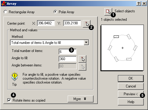
You can try this for yourself by drawing another rectangle as described above. This time, though, locate the rectangle in the centre top half of the drawing area. Now, start the Array command, click the Polar Array radio button and follow the steps below:
- Click the Select objects button. The dialogue box will temporarily disappear enabling you to select the rectangle you just drew. Press the Return button on your keyboard to complete the selection. You are now returned to the dialogue box and the message immediately below the Select Objects button should read "1 objects selected".
- Specify the center point for the array. This is the point C in the illustration below. You can do this by entering x and y co-ordinates into the appropriate edit boxes if you know what these values should be. However, this is rarely the case and most often you will want to click the Pick Center Point button to pick a point from the drawing area. Pick a point somewhere below the rectangle you have just drawn.
- Enter a value for the total number of items. For this example, enter the value "6". Notice that once again, the schematic preview updates to reflect the values you have entered.
- Make sure that the Rotate items as copied checkbox is checked.
 Click on the Preview button. Once again, the dialogue box disappears and the specified array is temporarily drawn so that we can preview it. We are now offered 3 choices. If the array isn't quite right, click the Modify button to return to the Array dialogue box. If you are happy with the array, click the Accept button, the array will be permanently drawn and the command is ended.
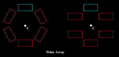
The array you have just drawn should look something like the one illustrated below, left. Take some time to play around with the other options in the Array dialogue box to see what they can do.

The illustration above shows the results of a polar array using an original rectangle (cyan) copied six times about a centre point C, through an angle of 360 degrees (full circle). The only difference between the array on the left and the one on the right is that the Rotate items as copied checkbox was not checked in the right hand example.
All new objects created with the Array command will inherit the object properties of the original object. See the "Object Properties" tutorial for information on object properties.


Your comment here:
Post a Comment