| Toolbar | none |
| Pull-down | |
| Keyboard | MLSTYLE |
The Multiline style command is used to create new multiline styles, which can then be used with the Multiline command. When you start the command for the first time, you will see the Multiline Styles dialogue box indicating that the Standard style is "Current". To create a new style, enter a new style name in the "Name" edit box by overwriting "STANDARD" and enter an optional description in the "Description" edit box. The dialogue box should now look something like the one on the right. When you are happy with the new name and description, simply click on the "Add" button. Your new style will now appear in the "Current" box. The new style you have created is simply a copy of the Standard style, so the next step is to change the style to suit your own purposes. Click on the "Element Properties…" button to proceed.
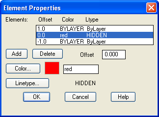
You will now see the Element Properties dialogue box appear. This dialogue box allows you to add new line elements or delete existing ones and to control the element offset, colour and linetype. Click the "Add" button to add a new element. A new line element now appears with an offset of 0.0, in other words, this is a centre line. Highlight the top element in the "Elements" list and change the offset to 1.0 by entering this value in the "Offset" edit box. Now do the same with the bottom element remembering to enter a value of -1.0 because this is a negative offset. You now have a multiline that is 2 drawing units wide with a centre line. Let's now change the colour and linetype of the centre line.
Highlight the 0.0 offset element by clicking it in the "Elements" list. To change the colour, simply click on the Colour… button and select an appropriate colour from the palette. When a colour has been selected, click the "OK" button on the palette to return to the Element Properties dialogue box.
Changing the linetype is a little more complicated because we will need to load the required linetype first. However, click on the "Linetype…" button to proceed.
The Select Linetype dialogue box appears with just a few solid linetypes listed, ByLayer, ByBlock and Continuous. Click on the "Load…" button. The Load or Reload Linetypes dialogue box now appears. Scroll down the list of linetypes until you find one called "Hidden". Highlight Hidden and then click the "OK" button. You will now see the Hidden linetype appear in the "Loaded linetypes" list in the Select Linetype dialogue box, which should now look similar to the one shown above. Finally, highlight Hidden and click the "OK" button. Your Element Properties dialogue box should now look similar to the one in the illustration above. To complete our new style, we will add some end caps and a solid fill. Click on the "Multiline Properties…" button to proceed.
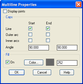
In the Multiline Properties dialogue box, click in the "Line" check boxes under "Start" and "End". This will have the effect of capping the ends of the multiline with a 90 degree line. As you can see from the dialogue box, you can change this angle if you wish to give a chamfered end. Next, click the "On" check box in the "Fill" section and then click on the Colour… button and select the fill colour from the palette. The Multiline Properties dialogue box should now look like the one in the illustration on the left. Finally, click the "OK" button in the Multiline Properties dialogue box and again in the Multiline Style dialogue box. You are now ready to draw with your new multiline.
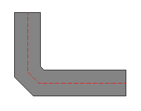
Start the Multiline command, pick a number of points and admire your handiwork. If you have followed this tutorial closely, your new multiline should look something like the one in the illustration on the right. Notice the effect of the various changes you have made compared with the Standard multiline style.
One limitation of multiline styles is that you cannot modify a style if there are multilines referencing the style in the current drawing. This is a shame because it means that it is not possible to update multiline styles in the same way as it is possible to update text or dimension styles. You also cannot change the style of an existing multiline. If you really want to modify a multiline style, you will have to erase all multilines that reference the style first.
If you are new to AutoCAD, the whole process of working with multilines and creating multiline styles may appear a little bewildering because it touches upon a number of aspects of the program with which you may not be familiar. If this is the case, it may be a good idea to return to this tutorial in the future. Multilines are useful because they can save lots of time but their use is fairly specific and you should think carefully before using them. It may, for example, be more convenient simply to draw a polyline and to create offsets using the Offset command.
| Toolbar | none |
| Pull-down | |
| Keyboard | MLSTYLE |
The Multiline style command is used to create new multiline styles, which can then be used with the Multiline command. When you start the command for the first time, you will see the Multiline Styles dialogue box indicating that the Standard style is "Current". To create a new style, enter a new style name in the "Name" edit box by overwriting "STANDARD" and enter an optional description in the "Description" edit box. The dialogue box should now look something like the one on the right. When you are happy with the new name and description, simply click on the "Add" button. Your new style will now appear in the "Current" box. The new style you have created is simply a copy of the Standard style, so the next step is to change the style to suit your own purposes. Click on the "Element Properties…" button to proceed.
You will now see the Element Properties dialogue box appear. This dialogue box allows you to add new line elements or delete existing ones and to control the element offset, colour and linetype. Click the "Add" button to add a new element. A new line element now appears with an offset of 0.0, in other words, this is a centre line. Highlight the top element in the "Elements" list and change the offset to 1.0 by entering this value in the "Offset" edit box. Now do the same with the bottom element remembering to enter a value of -1.0 because this is a negative offset. You now have a multiline that is 2 drawing units wide with a centre line. Let's now change the colour and linetype of the centre line.
Highlight the 0.0 offset element by clicking it in the "Elements" list. To change the colour, simply click on the Colour… button and select an appropriate colour from the palette. When a colour has been selected, click the "OK" button on the palette to return to the Element Properties dialogue box.
Changing the linetype is a little more complicated because we will need to load the required linetype first. However, click on the "Linetype…" button to proceed.
The Select Linetype dialogue box appears with just a few solid linetypes listed, ByLayer, ByBlock and Continuous. Click on the "Load…" button. The Load or Reload Linetypes dialogue box now appears. Scroll down the list of linetypes until you find one called "Hidden". Highlight Hidden and then click the "OK" button. You will now see the Hidden linetype appear in the "Loaded linetypes" list in the Select Linetype dialogue box, which should now look similar to the one shown above. Finally, highlight Hidden and click the "OK" button. Your Element Properties dialogue box should now look similar to the one in the illustration above. To complete our new style, we will add some end caps and a solid fill. Click on the "Multiline Properties…" button to proceed.
In the Multiline Properties dialogue box, click in the "Line" check boxes under "Start" and "End". This will have the effect of capping the ends of the multiline with a 90 degree line. As you can see from the dialogue box, you can change this angle if you wish to give a chamfered end. Next, click the "On" check box in the "Fill" section and then click on the Colour… button and select the fill colour from the palette. The Multiline Properties dialogue box should now look like the one in the illustration on the left. Finally, click the "OK" button in the Multiline Properties dialogue box and again in the Multiline Style dialogue box. You are now ready to draw with your new multiline.
Start the Multiline command, pick a number of points and admire your handiwork. If you have followed this tutorial closely, your new multiline should look something like the one in the illustration on the right. Notice the effect of the various changes you have made compared with the Standard multiline style.
One limitation of multiline styles is that you cannot modify a style if there are multilines referencing the style in the current drawing. This is a shame because it means that it is not possible to update multiline styles in the same way as it is possible to update text or dimension styles. You also cannot change the style of an existing multiline. If you really want to modify a multiline style, you will have to erase all multilines that reference the style first.
If you are new to AutoCAD, the whole process of working with multilines and creating multiline styles may appear a little bewildering because it touches upon a number of aspects of the program with which you may not be familiar. If this is the case, it may be a good idea to return to this tutorial in the future. Multilines are useful because they can save lots of time but their use is fairly specific and you should think carefully before using them. It may, for example, be more convenient simply to draw a polyline and to create offsets using the Offset command.
Read more»
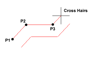
 key on the keyboard to be pressed to end them. In AutoCAD, clicking the right mouse key and selecting "Enter" from the context menu has the same effect as using the
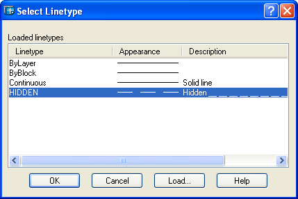
 The Scale option allows you to set a scale factor, which effectively changes the width of the multiline. The default scale factor is set to 1.0 so to half the width of the multiline, a value of 0.5 would be entered. A value of 2.0 would double the width.
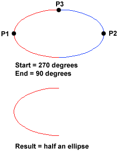 The Ellipse Arc command is very similar to the Ellipse command, described above. The only difference is that, in addition to specifying the two axis end points and the "distance to other axis" point, you are prompted for a start and end angle for the arc. You may specify angles by picking points or by entering values at the command prompt. Remember that angles are measured in an anti-clockwise direction, starting at the 3 o'clock position.
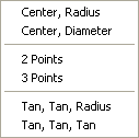
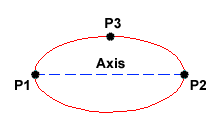 The Ellipse command gives you a number of different creation options. The default option is to pick the two end points of an axis and then a third point to define the eccentricity of the ellipse. After you have mastered the default option, try out the others.
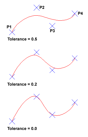 The Spline command creates a type of spline known as a nonuniform rational B-spline, NURBS for short. A spline is a smooth curve that is fitted along a number of control points. The Fit Tolerance option can be used to control how closely the spline conforms to the control points. A low tolerance value causes the spline to form close to the control points. A tolerance of 0 (zero) forces the spline to pass through the control points. The illustration on the right shows the effect of different tolerance values on a spline that is defined using the same four control points, P1, P2, P3 and P4.
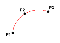 The Arc command allows you to draw an arc of a circle. There are numerous ways to define an arc, the default method uses three pick points, a start point, a second point and an end point. Using this method, the drawn arc will start at the first pick point, pass through the second point and end at the third point. Once you have mastered the default method try some of the others. You may, for example need to draw an arc with a specific radius. All of the Arc command options are available from the pull-down menu.
 As you can see from the command prompt above the default options are always indicated in triangular brackets like so
